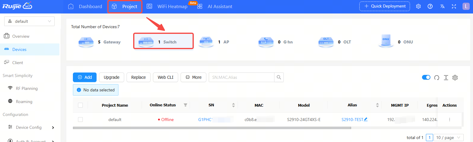
Click Project > Switch to go to the switch management interface. The switch device list will display the information of all switches in the current project by default.
Item Description:
(1) Project Name: Displays the name of the project where the device is located.
(2) Online Status: Displays the online status of the device. The status of the device includes: Online/Offline/Not Online Yet. Click the filter icon to filter devices by online status.
(3) SN: Displays the SN of the device. Click the SN number of a device to view its details.
(4) Configuration Status: Displays the configuration status of the device. Click the filter icon to filter the devices by configuration status.
(5) MAC: Displays MAC information of the device.
(6) Model: Displays device models.
(7) Alias: Displays aliases of devices.
(8) MGMT IP: Displays the management addresses of devices.
(9) Egress IP: Displays egress IP addresses of devices.
(10) Firmware Version: Displays firmware versions of the devices.
(11) Last See On: Displays last online time of devices.
(12) Action: Delete button is available in the Action column. Click the delete button to remove the device from the project.
Button Description
 : Add button. Click this button to enter the device adding interface.
 : Upgrade button.
 : Configuration replacement button. You can synchronize the configuration of an old device to a new one of the same model. After configuration replacement task is created, the configuration of the old device will be sent to the new one when it is online.
 : Click this button to display more operation buttons, including: Move, Delete, and Restart.
 : Automatic refresh button. The automatic refresh button is enabled by default. When it is enabled, the switch device list will automatically refresh once every minute.
 : Manual refresh button. Click this button to manually refresh the switch list.
 : Row height adjustment button. Click this button to manually refresh the switch list.
 : Click this button to customize the displayed items in the switch list.
 : Search box. Supports searching switches by SN, MAC, or alias.
Click the SN of a switch in the switch list to check its detailed information. The detailed interface consists of port panel, basic information, device overview, device port, configuration, PoE, diagnosis and downstream devices.

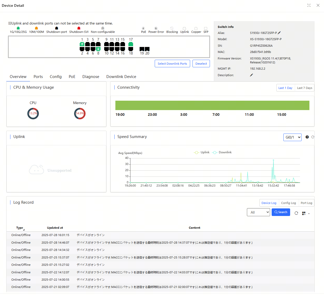
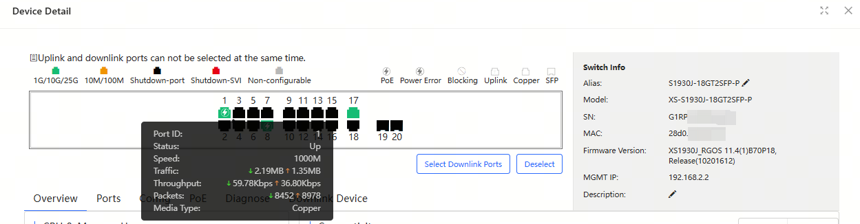
(1) Port Panel
The port panel displays the port type, status and speed. When you hover the cursor over a port, you can view its port ID, traffic, rate, type and other information of the port.
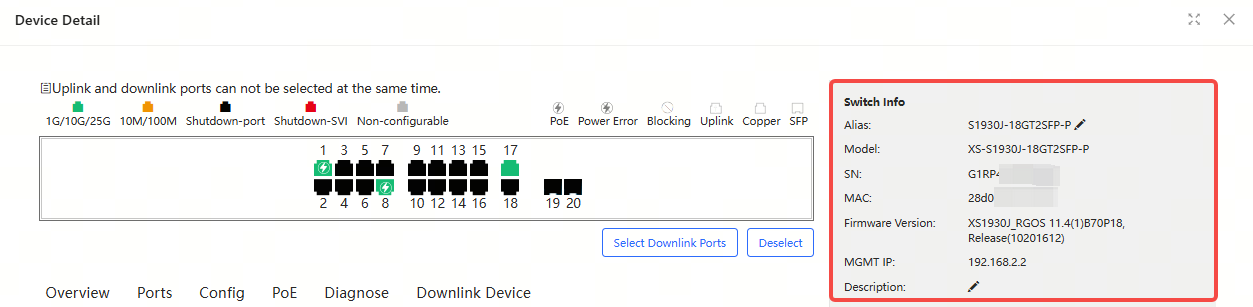
(2) Switch Information
The switch information table displays alias, model, SN, MAC address, firmware version, management IP and description. You can click the edit icon to modify the alias and description of the switch.
(3) Overview Tab
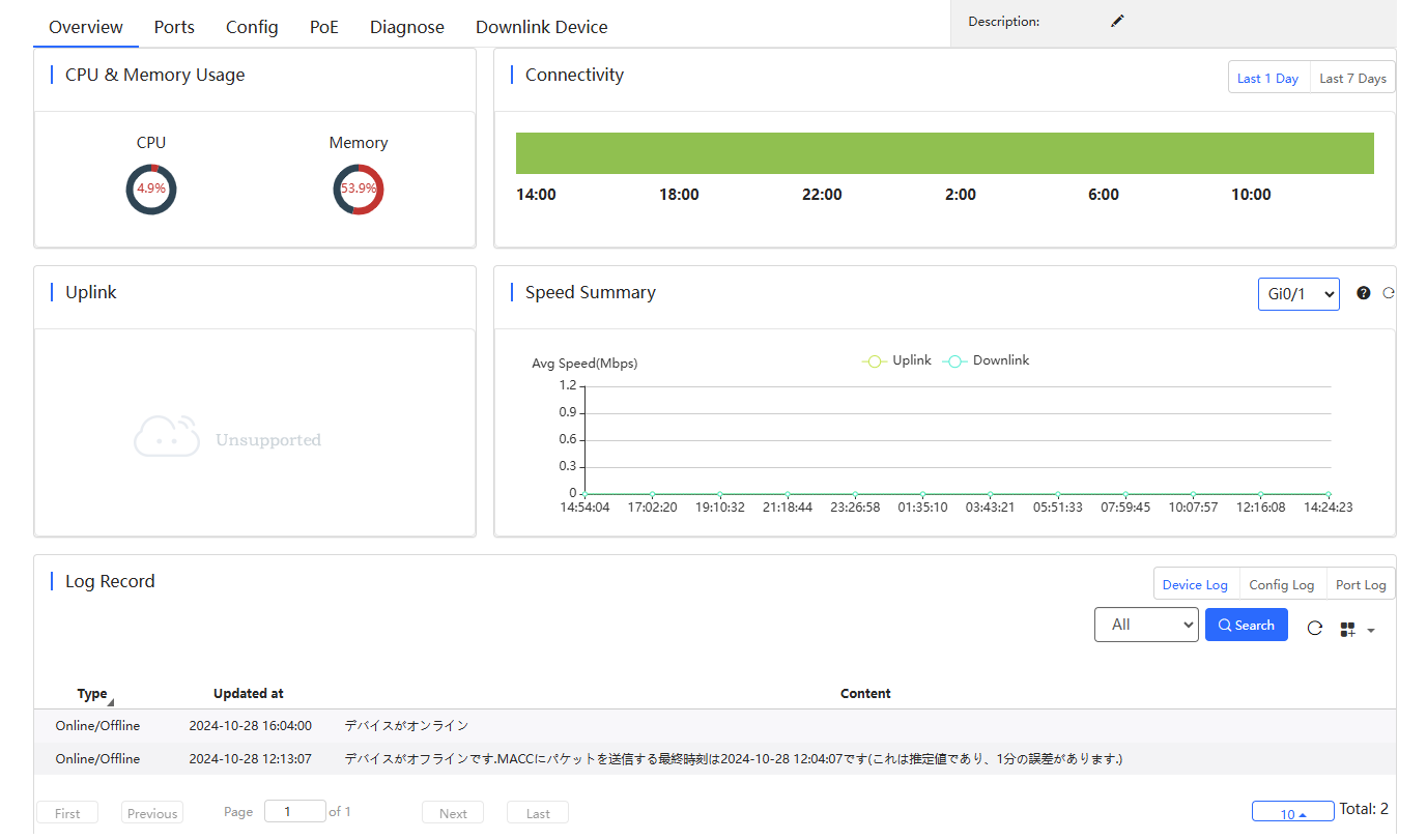
Displays the CPU and memory usages of the switch.
Displays the connection status between the switch and the Cloud in the last 1 day or 7 days.
Display uplink information, including port, speed, duplex, uplink/downlink speed, and uplink/downlink traffic.
Displays the device's uplink and downlink rates in the last 24 hours. Hover the cursor over a time in the chart to view the device's uplink and downlink rates at that time.
Support viewing three types of device logs, including device logs, configuration logs, and port logs. Logs can be filtered based on log types and time.
(4) Ports Tab
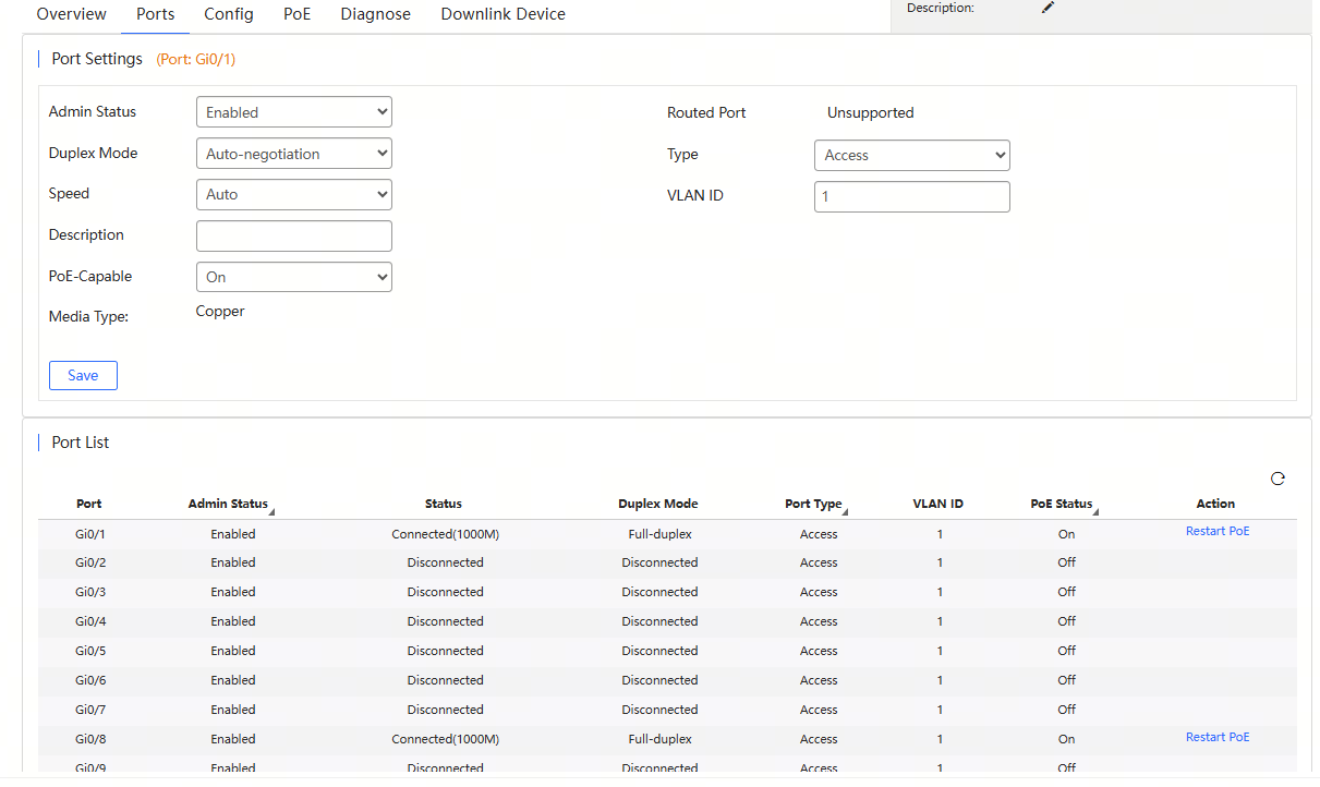
Support setting the port's admin status, duplex mode, speed, description, PoE, port type, and VLAN ID. After completing the settings, click Save.
The port list displays the information of all ports of the device, including port ID, management status, port status, duplex mode, port type, VLAN ID and PoE status. Click the icon of the Admin Status, Port Type and PoE Status to filter the port information.
(5) Configuration Tab
The Configuration tab consists of seven parts, including VLAN List, SVI&DHCP, DHCP Snooping, RLDP, Device Config, Service List and Configuration Backup List.
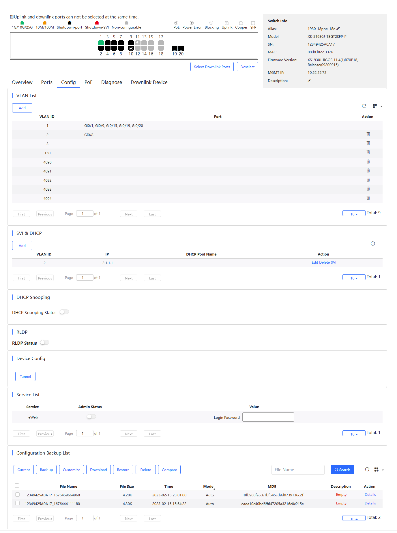
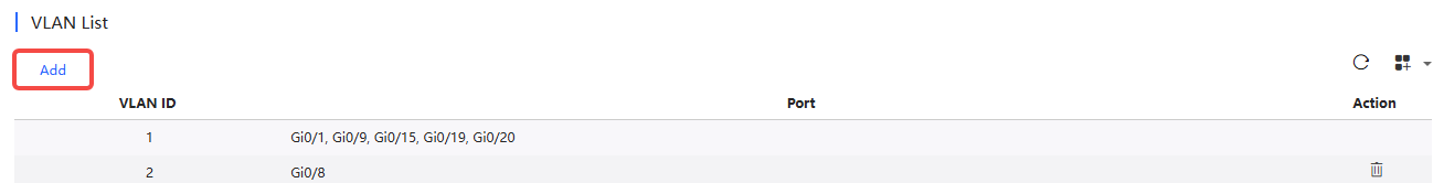
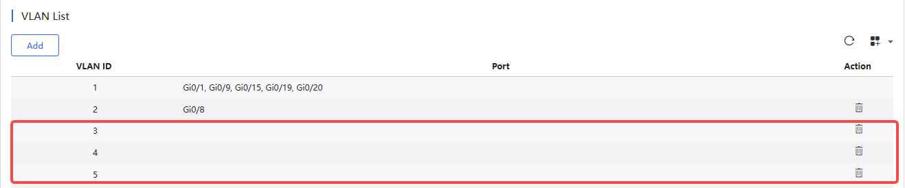
VLAN List displays the current VLAN ID and the corresponding port number. Click Add to add a VLAN ID.
The specific steps are as follows:
① Click Add.
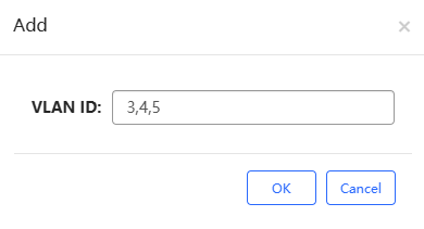
② Enter the VLAN ID.
Two methods are provided for you to add multiple VLAN IDs:
Method 1: Use commas (,) to separate VLAN IDs. Up to 10 VLAN IDs can be created at one time.
Method 2: Use dashes (-) to separate VLAN IDs. This method can be used to create VLANs in batches without any quantity limit, as long as the VLAN range is within 1-4094.
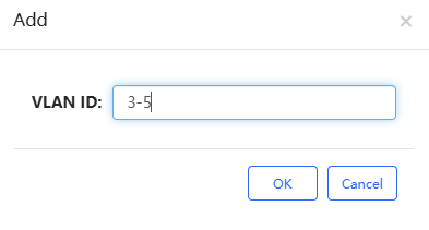
Note: Commas and dashes cannot be used together.
③ After setting the VLAN IDs, click OK. When the "Added succeeded" prompt appears, the operation is completed. The created VLAN ID will be displayed in the VLAN list. To delete a VLAN ID, click the delete icon in the Action column.
SVI & DHCP list displays the VLAN ID, SVI, and DHCP pool name.
Click Add, and configure the VLAN ID, IP and subnet mask, and then click Save.
Note: VLAN ID range is 1-4094.
DHCP Snooping is disabled by default. After enabling it, select a port and click Save. If the selected port is not a routing port, the uplink port is selected by default. If the port connected to the DHCP server is not an uplink port, you need to select it manually.
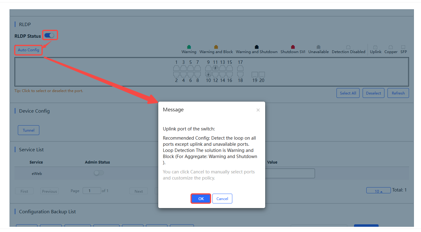
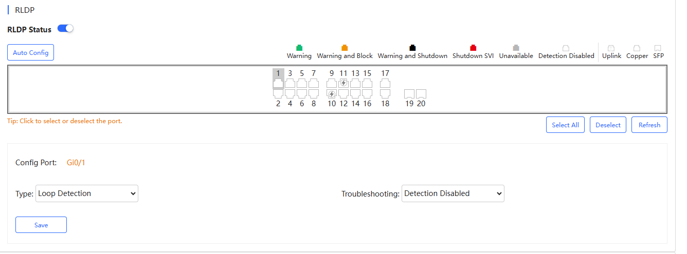
Rapid Link Detection Protocol (RLDP) is a link protocol used to quickly detect Ethernet link faults. After it is enabled, if a fault is detected, it will handle the fault according to the rule set on the device, including generating alarm, port shutdown, disabling the SVI where the port is located, etc. The RLDP is disabled by default. It supports automatic configuration and custom configuration.
Automatic Configuration:
① Enable RLDP status.
② Click Auto Config to use the system default configuration, that is, to perform loop detection on all ports except uplink ports and unavailable ports, and set the loop fault handling mode to Block and Alarm. For loops on aggregate ports, the fault handling mode is Alarm and Close.
③ Click OK in the confirmation box to complete the operation.
Custom Configuration:
① Enable RLDP Status.
② Select the port(s) to be detected. If you want to select all ports, click Select All. To cancel the selection, click Deselect.
③ Select a troubleshooting method. Five troubleshooting methods are provided: Detection Disabled, Warning, Block, Shutdown-port, and Shutdown-SVI. Before setting the troubleshooting method to Warming, make sure that the RLDP alarm has been enabled in the Alarm Settings interface. The alarm setting function will be supported in the future.
④ After selecting the port(s) and configuring the troubleshooting method, click Save. When the "Save Succeeded" prompt appears, the operation is completed.
In the Device Configuration interface, you can create a tunnel.
Click Tunnel to enter the tunnel creation interface. Fill in the destination address of the tunnel, select the tunnel type and port, and then click Create Tunnel.

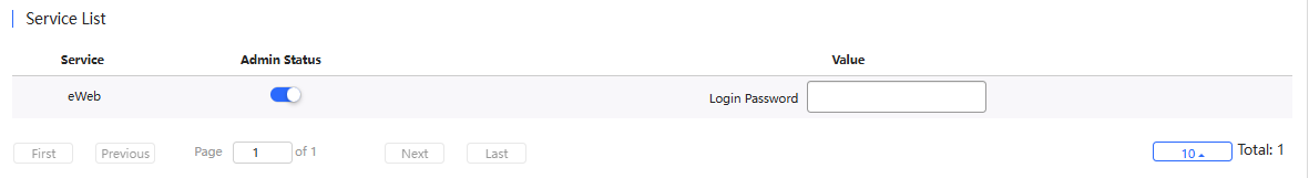
Supports configuring account status and login password of the device’s eWeb. The password length is 8-31 characters.
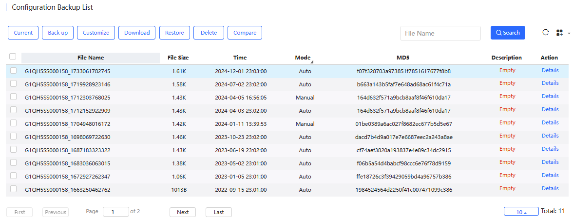
Supports backing up configuration. The information displayed in the backup list includes configuration file name, file size, time, mode, MD5 and description.
 \
\
Button Description:
(1) Current: Click this button to display the current configuration of the device. If you want to back up the configuration, click Backup in the Config Details interface. After backup, click to refresh the list, and the backed up file will be displayed in the list.
(2) Back up: Click this button to back up the current configuration of the device. When the operation confirmation box appears, click OK. After backup, click to refresh the list, and the backed up file will be displayed in the list.
(3) Customize: Configuration file customization button. Select one of the files in the Configuration Backup List, and then click this button to modify the configuration. After setting the file name and changing the configuration, click Save to complete the operation.
(4) Download: Configuration file download button. Select a configuration file in the Configuration Backup List, and click Download to download the configuration file. When the operation confirmation box appears, click OK. Only one configuration file can be downloaded at a time.
(5) Restore: Backup file restore button. Check a configuration file and click Restore to restore the current configuration file of the device to the selected configuration file. Only one file can be restored at a time.
(6) Delete: Delete button. Select a configuration file to be deleted, click Delete, and when the operation confirmation box appears, click OK to delete the configuration file.
(7) Compare: Comparison button. Select two configuration files to be compared and click Compare to compare the two profiles to find out their differences.
(8) Details: Click this button in the Action column to view the detailed configuration of a file.
(9) Description: Click the words in the Description column to modify the profile description.
(6)PoE
The PoE statistics are displayed above the PoE list, including total power, current power, and time.
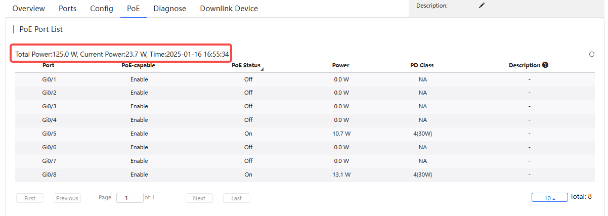
To shut down the PoE port at a specific time:
Step 1: Click Add.
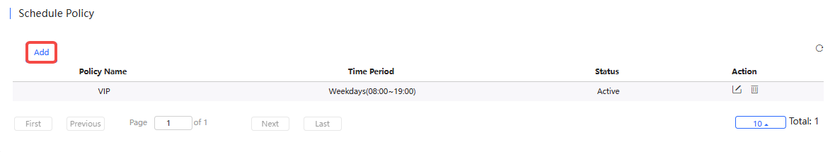
Step 2: Set the policy name and specify the time period.
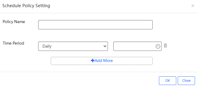
(1) Policy Name: (Required) Set the policy name.
(2) Time Period: (Required) Set the time period.
(3) + Add More: Click it to set multiple time periods.
Step 3: Click OK.
Click the edit icon in the Action column to modify the priority, maximum power, and power supply stop policy.

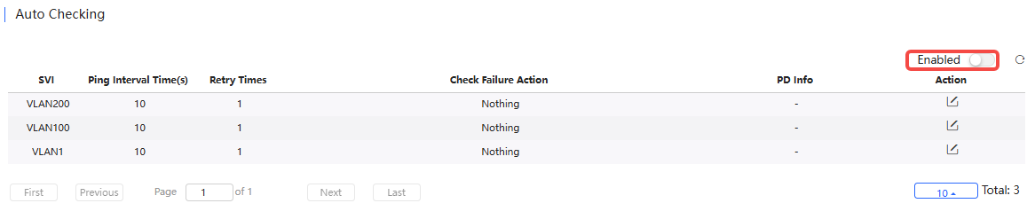
After the PoE self-check function is enabled, the system will automatically detect the configured ports. When the PD device is detected to be offline, a trap notification is sent by default; if the reboot-remote-pd option is configured, it will automatically restart the PD device.
(7) Diagnose
Supports port fault detection. The specific steps are as follows:
Step 1: Select the type.
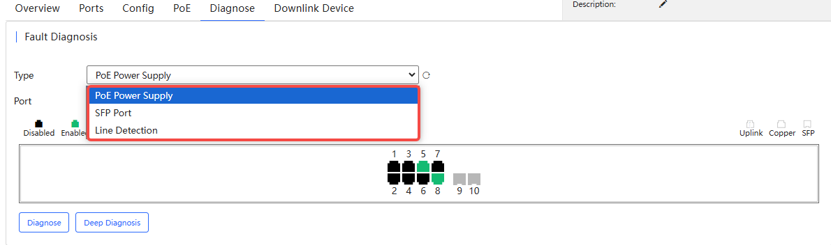
Step 2: Select the port to be diagnosed on the panel and the diagnosis type.
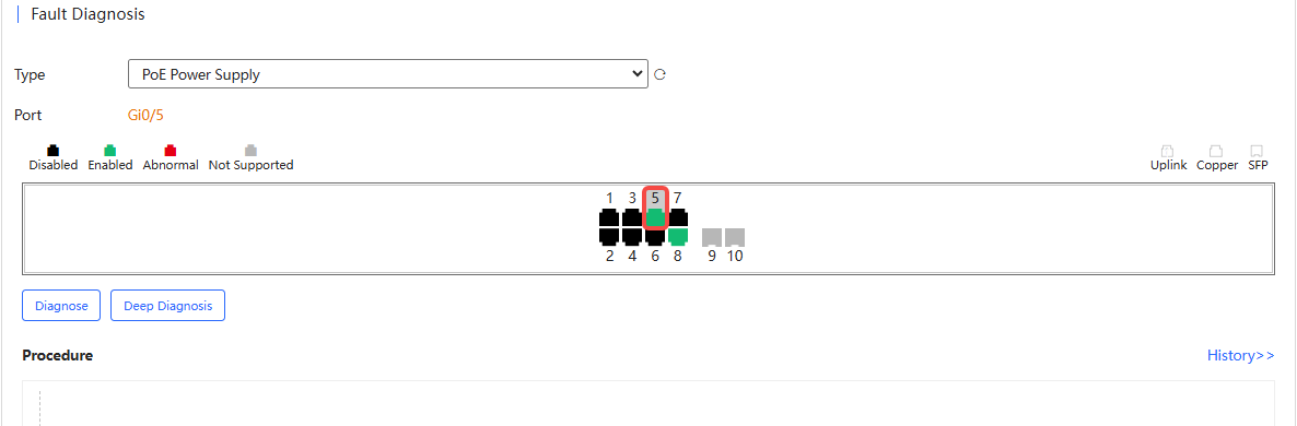
Diagnose Type:
Diagnose: The cloud server sends CLI commands to collect switch information, and the diagnosis is performed on the cloud server.
Deep Diagnose: Diagnostics are performed on the switch and the results are reported to the cloud server.
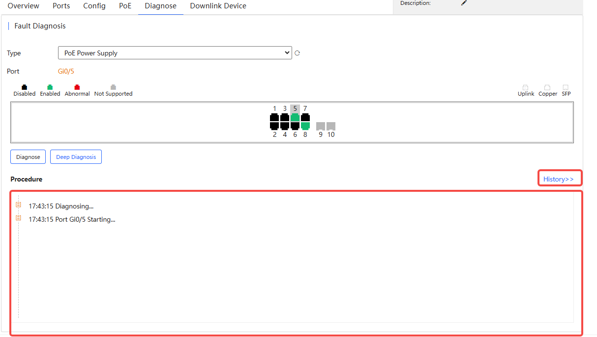
Step 3: Waiting for the diagnosis result. Click to display the historical records.
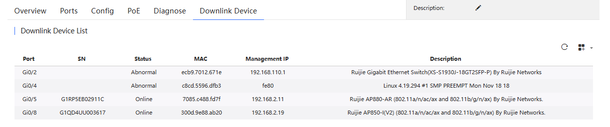
(8) Downlink Device
Display the downlink device information of the switch.
全部评论